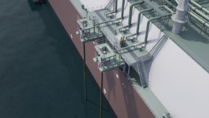
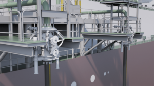
SUPPORT SKID
The package proposed includes a structural steelwork skid assembly for mounting directly to pre‐installed foundations on the vessel deck.
The purpose of the skid is to house the following:
- Structural support the upper QCDC and ball valve unit.
- Interface between the QCDC and the deck piping. Outlet from the rear of the skid will be a suitably positioned flange. A manually operated ball valve to isolate the piping when out of operation will also be included at the deck piping interface.
- Dual pull‐in winches, mounted above the QCDC set to match the centers of the dual pull‐in post/funnels.
- Frame‐work to support the hose end buoyancy module.
- Suitable personnel access platform for normal connection and disconnection of the QCDC, inspection and maintenance of the equipment, etc.
- Ladders, rails, etc. for access to the winches (located on top of the skid structure) for inspection and maintenance.
- The hydraulic control manifold and piping for the QCDC and winch operations.
It is possible, dependent upon the amount of available deck space in the vicinity of the offloading location, that the skid be extended to also house the hydraulic power/control unit.
The skid assembly will include all necessary pipe work and electrical cable required for the operation of all components, for status indication and remote activation. All lines will terminate in a common bulkhead plate(s) and junction box(es) for the interconnection to other elements of the system (by others).
Upon an emergency release of the HP jumper and hose side ball valve a hydraulic braking/retarding system installed on the skid, with a rope connected to a shackle on the valve protection cage, controls the speed of descent of the jumper and ball valve. This prevents damage to the hose side valve by eliminating heavy impacts with the vessel’s hull, etc.


